Building up to the pipeline
The first version was deliberately small: an ALU, register file, program counter, and instruction memory with focused testbenches around the pieces I could reason about independently. I connected those blocks into a simple top level before introducing pipeline registers. That sequence mattered because it gave me a working reference for decode and execution before timing became part of the problem. From there I moved through a three-stage implementation and eventually split the design into the conventional IF, ID, EX, MEM, and WB stages.
- IFu_pcu_imem
- IF / ID
u_if_id - IDdecoderu_regfileu_hazard
- ID / EX
u_id_ex - EXu_forwardingu_aluredirect
- EX / MEM
u_ex_mem - MEMu_dmemlane select
- MEM / WB
u_mem_wb - WBresult muxregister write
Once the five stages were in place, I had to treat the control signals as data that travel with each instruction. A register write enable generated during decode, for example, cannot act on the register named by whatever instruction happens to be in decode several cycles later. The destination register, ALU operation, memory controls, immediates, and source values all cross the same stage boundaries as the instruction they describe. Many early pipeline failures traced back to a correct value arriving in the wrong cycle.
Forward when the value exists
Data hazards were the first place where the pipeline stopped behaving like five independent steps. A dependent instruction may need a register value several cycles before writeback, even though the result already exists elsewhere in the processor. NOVA-1 forwards from EX/MEM first and falls back to MEM/WB. EX/MEM receives priority because it contains the newest result when multiple older instructions target the same register.
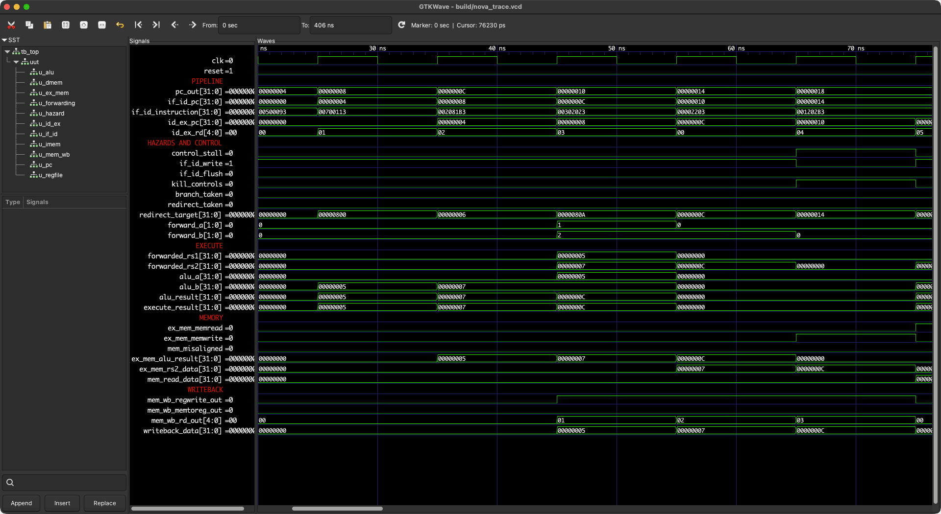
Loads follow a different timing path. Execute produces the address, and memory returns the requested value during the following stage. Forwarding the EX/MEM ALU result would send that address to the dependent instruction. The forwarding unit blocks that path, and the hazard unit handles the dependency by freezing the program counter and IF/ID register for one cycle while injecting inert controls into ID/EX. Decode also records whether each opcode uses rs1 or rs2, preventing false stalls when those bit positions encode an immediate or destination field.
Recovering from control flow
Conditional branches, JAL, and JALR resolve in the execute stage. By that point the fetch and decode stages already contain younger instructions from the sequential path. When a redirect is taken, the core selects the new program counter, flushes IF/ID, and kills the controls entering ID/EX so those wrong-path instructions cannot update a register or memory later. The redirect is also allowed to override a simultaneous front-end stall; once the correct target is known, holding the old program counter would preserve work the processor has already proved invalid.
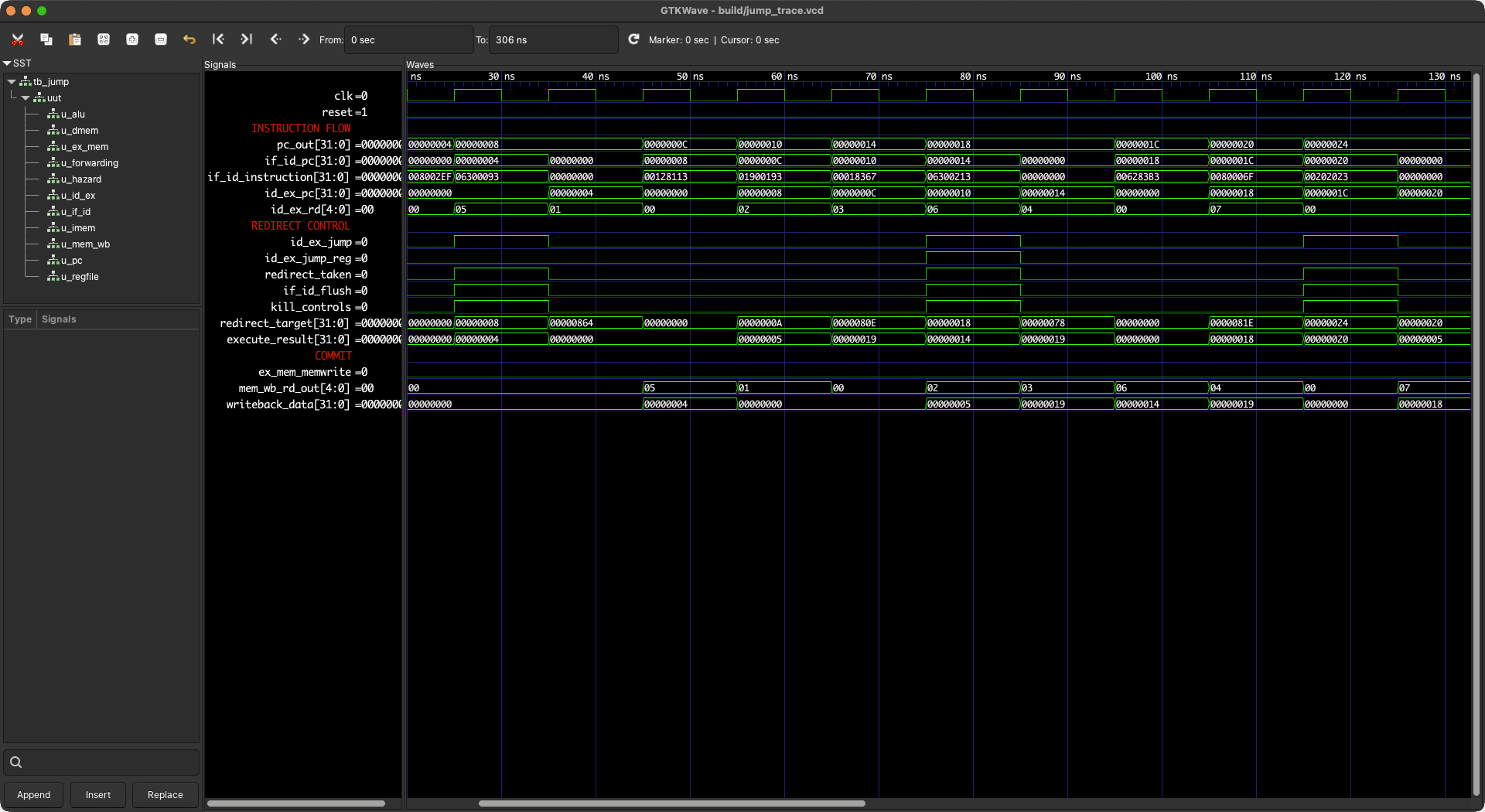
The branch comparator uses forwarded operands, which lets a branch depend on a recent ALU result without waiting for it to reach the register file. Signed and unsigned comparisons are handled separately for BLT, BGE, BLTU, and BGEU. JAL and JALR reuse the same redirect path while carrying PC + 4 forward as the link value, and JALR clears the low target bit as required by the ISA. I tested the path with instructions and stores placed immediately after jumps, since those are the operations that expose an incomplete flush most clearly.
Growing the instruction set
I added instructions in groups that exercised a shared piece of the datapath. Register and immediate ALU operations established the decode and forwarding paths. LUI selects zero as the first ALU operand, and AUIPC selects the instruction's program counter. JAL and JALR added link values and redirects. Each group corresponded to a specific datapath change, which kept the decoder organized as the supported subset grew.
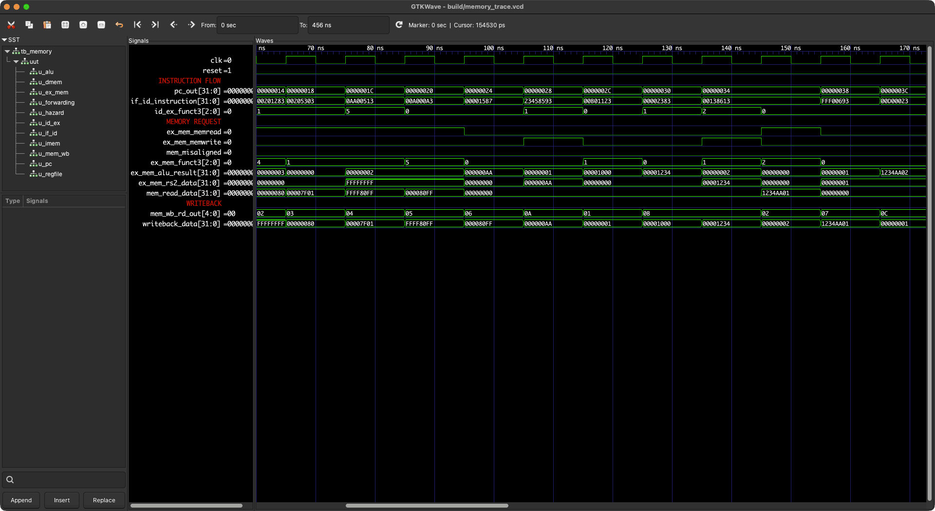
The memory path supports LB, LH, LW, LBU, LHU, SB, SH, and SW over a 1 KiB data memory. The low address bits select a byte or halfword lane, loads apply the correct sign or zero extension, and stores preserve the untouched lanes of the word. Trap handling remains outside the current scope. Misaligned halfword and word loads return zero, and matching stores are suppressed, giving those accesses deterministic behavior without corrupting memory.
Verifying the complete pipeline
The early testbenches were directed and local. They checked the ALU, program counter, individual instruction families, forwarding, load-use stalls, and control-flow flushing with known inputs and expected outputs. Those tests are still useful because a failure usually points to one area. Their limitation is coverage: a pipelined processor can pass every isolated instruction test and still fail when several valid instructions create an unexpected dependency across multiple stages.
To cover that gap, I added a deterministic differential test. A Python generator builds programs containing arithmetic, shifts, comparisons, loads, stores, all six branch conditions, upper-immediate operations, and jumps. The same program runs through an independent architectural reference model and the Verilog core. At the end, the testbench compares all 32 registers and every data-memory word. A fixed seed keeps failures reproducible. Additional seeds explore new instruction sequences without requiring a hand-written test for each one.
Using waveforms to explain the failure
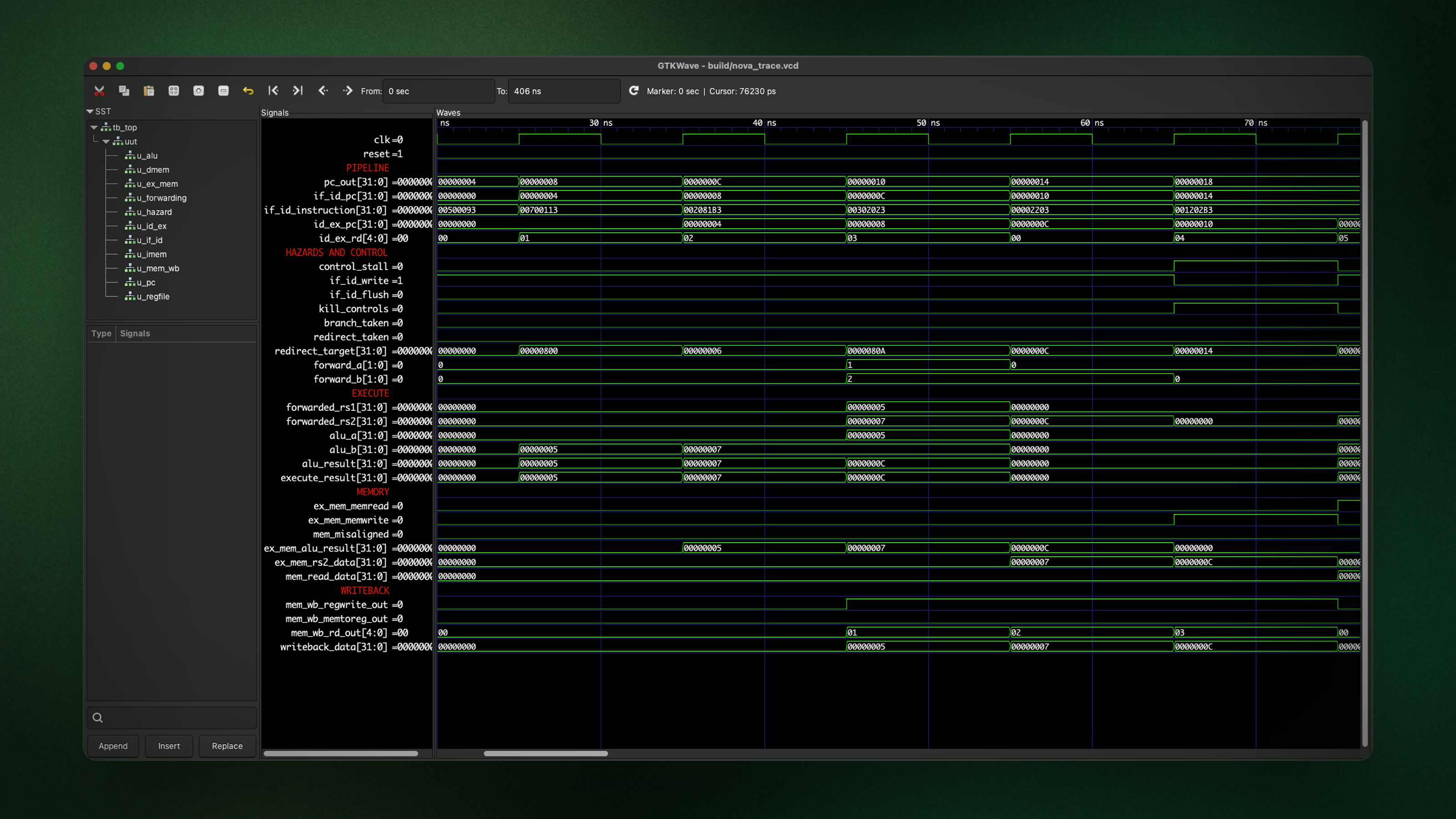
Waveforms were most useful after a self-checking test told me that the final state was wrong. I organized the GTKWave view around instruction flow: program counters and instructions first, followed by forwarding selections, stall and redirect controls, ALU results, memory activity, and writeback. That arrangement lets me follow one instruction horizontally through time and see why a later instruction received a particular operand.
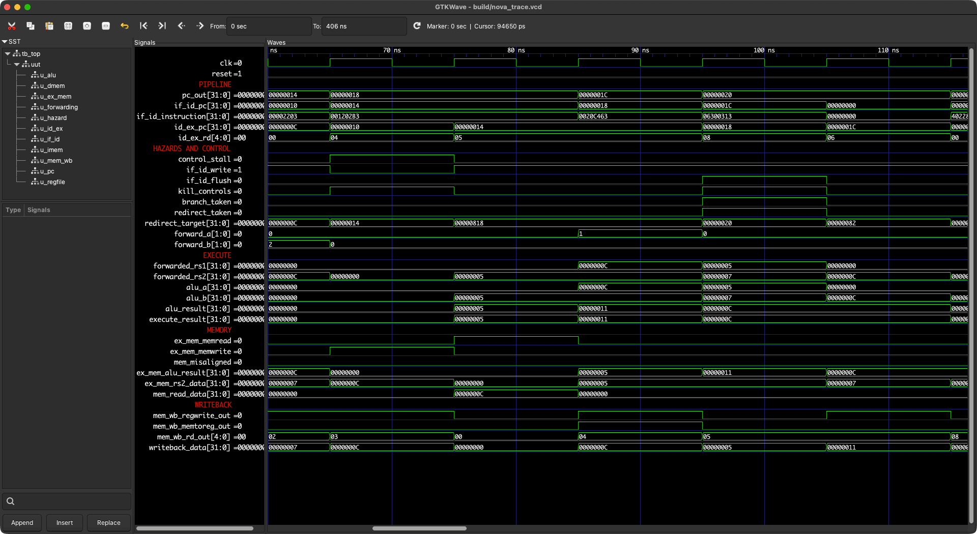
The repository includes a short trace designed around three cases that were easy to confuse in a larger program. Forwarding appears around cycles five and six, a load-use dependency forces the interlock around cycles seven through nine, and a taken branch shows the redirect and recovery around cycles ten and eleven. Keeping that trace small made it useful as both a debugging fixture and a record of how the hazard machinery is supposed to behave.
Checking that the RTL is buildable
I added a generic Yosys synthesis flow for the complete core so the hierarchy is elaborated as hardware and checked for inferred latches, conflicting drivers, and disconnected logic. The simulation suite and synthesis check run in GitHub Actions, giving every change the same baseline verification.
yosys -p "synth -top top -noabc; stat"=== top === Number of wires: 6,361 Number of wire bits: 29,779 Number of cells: 27,209 Number of submodules: 11 $_MUX_ 9,353 $_DFFE_ 9,280 $_AND_ 4,485 $_OR_ 3,079 $_XOR_ 386 $_DFF_ 339 $_NOT_ 287
The generic synthesis target confirms that Yosys can lower the RTL into a netlist. Device-specific clock limits, resource use, and board readiness require an FPGA family, mapped memories, timing constraints, and pin assignments. Those steps belong to hardware implementation and remain future work for NOVA-1.
Where I would take it next
NOVA-1 now has a stable five-stage pipeline, a substantial RV32I subset, automated architectural checks, and a repeatable synthesis path. The current scope excludes exceptions, privilege levels, CSRs, and memory-mapped peripherals, and the memories remain small simulation-oriented blocks. The next practical step is selecting an FPGA target, mapping the memories, adding timing and pin constraints, and connecting a small UART to the memory bus.
I would measure the baseline implementation before adding prediction. Execute-stage branch resolution currently creates a visible control penalty. A predictor would add state, recovery rules, and new verification cases, so FPGA measurements should establish the branch frequency and timing baseline first. Those results would provide a concrete comparison for the predicted design and guide the next architectural change.